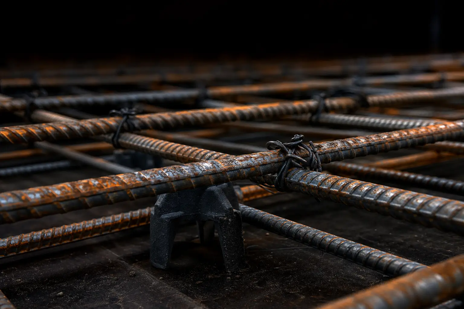
How to Do a Rebar Takeoff
A rebar takeoff counts every reinforcing bar on the structural drawings by size, works out each bar's length including hooks and laps, totals the linear feet by size, and multiplies by the unit weight to get pounds and tons. The steel is priced by weight, so the final number is tons by bar size, plus a separate list of accessories: chairs, dowels, tie wire, and mesh.
The whole process fits in six steps:
1. Read the general notes and schedules first. Concrete strength, rebar grade, lap lengths, cover, and typical details all live there, and they change every number downstream.
2. Break the job into elements. Footings, walls, slabs, columns, beams, piers. Each element type has its own counting formula.
3. Count bars per element. Bars at a spacing are (clear length / spacing) + 1. Continuous bars are the run length. Ties and stirrups are the member length divided by spacing, plus one.
4. Figure each bar's length. Clear dimension minus cover at both ends, plus hook detailing length, plus a lap wherever the run is longer than the bar you can buy.
5. Total by size and convert to weight. Linear feet times pounds per foot, divided by 2,000 for tons.
6. Add accessories and waste. Chairs, bolsters, dowels, tie wire, corner bars, and a cutoff allowance that you can defend.
Know Which Kind of Takeoff You Are Doing
Estimators use the word "takeoff" for two different jobs. A bid takeoff is what you build from the structural drawings to price the work. A bar list is what the rebar detailer builds from those same drawings for the fabricator, bar by bar, with marks, bend shapes, and cut lengths. Per ACI 315, the engineer shows the design on the structural drawings, including lap locations and lengths, and the detailer turns that into placing drawings and bar lists that get submitted for approval.
Your bid takeoff will never be as exact as the detailer's bar list, and it does not need to be. It needs to be close enough that the detailer's list does not blow your number. That means counting every element, carrying real hooks and laps instead of a flat percentage, and knowing where the steel hides.
The One Formula You Will Use Most
Pounds = Linear feet x Unit weight (lb/ft)
A #4 bar weighs 0.668 lb per foot. A #5 weighs 1.043. Those two numbers alone cover most residential and light commercial work. The full table is in the cheat sheet below.
Reading Rebar on the Drawings
Rebar information is scattered across the structural set. Nobody puts it all in one place, and the takeoff falls apart when you miss one of the sources.
Where to Look
| Sheet or source | What it gives you | What people miss |
|---|---|---|
| General notes (usually S-001) | f'c, rebar grade, lap schedule, cover, hook standard | Top-bar lap factor, epoxy requirements, "provide corner bars at all intersections" |
| Foundation plan | Footing marks, grade beams, piers, slab reinforcing callouts | Thickened slab edges and interior bearing footings |
| Footing and pier schedules | Bar size, count, and length per footing mark | Dowels shown only in the section, not the schedule |
| Wall sections and typical details | Verticals, horizontals, dowels, hooks | Bars at openings, wall-to-footing dowels |
| Column schedule | Vertical bars, tie size and spacing, splice zones | Tighter tie spacing at top and bottom of the column |
| Slab plans | Top and bottom mats, bar direction, extra bars at openings | Top bars over beams and supports, drawn short and easy to skip |
Reading a Callout
A typical callout reads something like #5 @ 12" O.C. E.W., T&B. Break it down:
- -#5 is the bar size, which is the diameter in eighths of an inch. A #5 is 5/8 inch.
- -@ 12" O.C. is the spacing, 12 inches on center.
- -E.W. means each way. You have two layers of bars, one in each direction.
- -T&B means top and bottom. Now you have four layers.
That one callout on a mat footing is four separate counts. Miss the T&B and you are short half the steel.
Other shorthand you will see: CONT. for continuous (run the full length with laps), EQ. SPA. for equal spacing (divide the length evenly, count still needs the plus one), STD. HK. for standard hook, and DWL for dowel.
Bar Marks
On placing drawings and bar lists, bent bars carry a mark. The Indiana DOT bar bending standard (consistent with ACI 318 and the CRSI Manual of Standard Practice) uses a numbering system where a mark like 588 reads as bar size 5, mark number 88. Straight bars are designated by size and length only. You will not usually write marks in a bid takeoff, but reading them lets you check a detailer's list against your own quantities later.
When the Drawings Are Incomplete
On plan sets for small jobs, the structural information is often thin. You may get a typical footing section and nothing else. When that happens, take off exactly what is shown, then list what you assumed in the proposal. If you assume #4 dowels at 48 inches because a local code requires it and the drawings are silent, write that down. An assumption on paper is a change order waiting to happen. An assumption in your head is money you are giving away.
Bar Data Cheat Sheet: Weights, Cover, Hooks
Pin this section. These three tables answer most of the questions that come up mid-takeoff.
ASTM Bar Sizes and Weights
From the CRSI standard reinforcing bar table (ASTM nominal dimensions):
| Bar size | Diameter (in) | Area (sq in) | Weight (lb/ft) | 20 ft bar (lb) | Linear ft per ton |
|---|---|---|---|---|---|
| #3 | 0.375 | 0.11 | 0.376 | 7.5 | 5,319 |
| #4 | 0.500 | 0.20 | 0.668 | 13.4 | 2,994 |
| #5 | 0.625 | 0.31 | 1.043 | 20.9 | 1,918 |
| #6 | 0.750 | 0.44 | 1.502 | 30.0 | 1,332 |
| #7 | 0.875 | 0.60 | 2.044 | 40.9 | 978 |
| #8 | 1.000 | 0.79 | 2.670 | 53.4 | 749 |
| #9 | 1.128 | 1.00 | 3.400 | 68.0 | 588 |
| #10 | 1.270 | 1.27 | 4.303 | 86.1 | 465 |
| #11 | 1.410 | 1.56 | 5.313 | 106.3 | 376 |
The last two columns are just arithmetic from the weight per foot. Linear feet per ton is 2,000 divided by the unit weight, handy for sanity-checking a supplier quote or a tonnage from a detailer.
Concrete Cover
Cover is the concrete between the bar and the face of the concrete. It comes off both ends of every bar, so it changes your bar lengths and sometimes your bar count. The values below are the CRSI summary of ACI 318 for cast-in-place, non-prestressed concrete. ACI 318-19 Table 20.5.1.3.1 is the governing table, and ACI's own FAQ notes the 3 inch requirement against earth dates back to the 1920 code.
| Condition | Bar size | Minimum cover |
|---|---|---|
| Cast against and permanently in contact with earth (footings, grade beams) | All | 3 in |
| Exposed to earth or weather (formed walls below grade, exterior walls) | #6 through #18 | 2 in |
| Exposed to earth or weather | #5 and smaller | 1-1/2 in |
| Interior slabs, walls, joists, not exposed | #11 and smaller | 3/4 in |
| Interior beams and columns, to ties or stirrups | All | 1-1/2 in |
The drawings can call for more than these minimums, and on parking structures and marine work they often do. Use the general notes over this table every time.
Standard Hook Dimensions
A hook adds length that never shows up on the plan dimension. The CRSI standard hook card gives the detailing dimension, which is the extra length the bar needs to form the hook, measured out to out:
| Bar size | Min. bend diameter (D) | 90 degree hook, add | 180 degree hook, add | 180 degree hook, J (out-to-out height) |
|---|---|---|---|---|
| #3 | 2-1/4 in | 6 in | 5 in | 3 in |
| #4 | 3 in | 8 in | 6 in | 4 in |
| #5 | 3-3/4 in | 10 in | 7 in | 5 in |
| #6 | 4-1/2 in | 1 ft 0 in | 8 in | 6 in |
| #7 | 5-1/4 in | 1 ft 2 in | 10 in | 7 in |
| #8 | 6 in | 1 ft 4 in | 11 in | 8 in |
Stirrups and ties bend tighter and use shorter hooks. Per the same CRSI card, a 90 degree stirrup or tie hook adds about 4 inches on a #3, 4-1/2 inches on a #4, and 6 inches on a #5. A 135 degree hook adds about 4 inches on a #3, 4-1/2 on a #4, and 5-1/2 on a #5.
Notice that the 90 degree end hook is the longer one. A #6 with a 90 at each end carries 2 extra feet of bar that is not on any plan dimension. Across a few hundred footing dowels that is real tonnage.
Counting Bars by Element
Every element comes down to two questions: how many bars, and how long is each one. The formulas change a little by element.
Slabs and Mats
Number of bars = (Clear length / Spacing) + 1
Clear length is the dimension you are spacing across, minus the edge cover at both sides. Bar length is the dimension the bar runs along, minus cover at both ends.
Say a 30 ft by 50 ft slab has #4 at 12 inches each way, with 3 inches of clearance at the edges (0.25 ft per side, 0.5 ft total):
- -Bars running 50 ft, spaced across 30 ft: (29.5 / 1) + 1 = 30.5, round up to 31 bars at 49.5 ft = 1,534.5 LF
- -Bars running 30 ft, spaced across 50 ft: (49.5 / 1) + 1 = 50.5, round up to 51 bars at 29.5 ft = 1,504.5 LF
- -Total: 3,039 LF x 0.668 = 2,030 lb before laps
A quick check from CalcHQ's rebar guide: a 12 inch grid each way runs about 2 LF of bar per square foot of slab. 1,500 SF x 2 = 3,000 LF. That lines up, so the count is probably right.
Continuous Footings and Grade Beams
Longitudinal bars are the footing run length times the number of bars in the section. Measure on the centerline so corners are not counted twice. If there are transverse bars across the footing width, count them like slab bars along the footing length, and take their length as footing width minus 3 inches of cover each side.
Walls
Walls are two slab grids stood on end, one direction vertical and one horizontal:
- -Verticals = (Wall length / Spacing) + 1 per layer, at a length of wall height plus dowel lap at the bottom, minus top cover
- -Horizontals = (Wall height / Spacing) + 1 per layer, at the wall length plus laps
Walls 10 inches and thicker often get two curtains, one near each face. A callout of "#5 @ 12 E.W., E.F." (each face) is four sets of bars, not two.
Columns and Ties
Vertical bars are a count straight off the column schedule, times the column height plus the lap or dowel at the base. Ties are where people lose time. The length of one tie is its out-to-out perimeter plus two hooks:
Tie length = 2 x (Width - 2 x cover) + 2 x (Depth - 2 x cover) + 2 x hook
For a 16 by 16 inch column with 1-1/2 inch cover to the ties and #3 ties with 135 degree hooks:
- -Tie size out to out: 16 - 3 = 13 in each way
- -Perimeter: 4 x 13 = 52 in
- -Two 135 degree hooks at about 4 in each for a #3: 8 in
- -Tie length: 60 in = 5.0 ft, or 1.88 lb per tie at 0.376 lb/ft
Tie count is (Column height / Spacing) + 1. Check the schedule for tighter spacing at the top and bottom of the column. In seismic work that confinement zone can hold as many ties as the rest of the column.
Piers and Drilled Shafts
Verticals are a straight count times depth plus the dowel into whatever sits on top. Spirals and hoops follow the tie logic using the circumference: pi x (Diameter - 2 x cover) per hoop, plus the lap.
Beams
Bottom bars, top bars at supports, and stirrups. Top bars over supports are usually drawn as short bars extending a set distance each side of the support. They are easy to miss because they do not run the full span. Stirrups count and size exactly like column ties.
This element-by-element counting is the tedious part, and it is the part Tectonic handles: it reads the plan set and pulls the material quantities for you, then applies your overhead and profit markup. Count one foundation by hand first anyway. You need to know what the right answer looks like before you trust any tool to give it to you.
Laps, Stock Lengths, and Waste
Laps are where rebar takeoffs go most wrong, because the rule of thumb and the code can be far apart.
Stock Lengths Drive Lap Count
Straight rebar in the US is commonly stocked in 20, 40, and 60 foot lengths. Twenty-foot sticks are what most yards and suppliers keep on hand for small jobs. Any run longer than the bar you are buying needs a splice, and every splice consumes a lap length of extra steel.
The lap count for a run is:
Laps = Number of bars in the run - 1
To find the number of bars, remember that each stick after the first only adds its length minus one lap. With #4 at a 30 inch lap on 20 ft sticks, the first stick covers 20 ft and each additional stick covers 17.5 ft.
How Long Is a Lap Splice?
The structural drawings govern. Look for a lap schedule in the general notes. If you have to estimate before you get one, here is what ACI 318's simplified development length method gives for a Class B tension splice with Grade 60, uncoated bars in normal-weight concrete, non-top bars, with adequate cover and spacing. Class B is 1.3 times the development length with a 12 inch minimum.
| Bar size | f'c = 3,000 psi | f'c = 4,000 psi | 40 bar diameters (rule of thumb) |
|---|---|---|---|
| #3 | 22 in | 19 in | 15 in |
| #4 | 29 in | 25 in | 20 in |
| #5 | 36 in | 31 in | 25 in |
| #6 | 43 in | 37 in | 30 in |
| #7 | 63 in | 54 in | 35 in |
| #8 | 72 in | 62 in | 40 in |
The math behind it, for #6 and smaller, is development length = (60,000 / (25 x square root of f'c)) x bar diameter. For #7 and larger the 25 becomes 20, which is why the lap jumps between #6 and #7. Multiply by 1.3 for Class B. Those values match the Field PM lap chart built from the same method.
Look at the last column. The common 40 bar diameter field rule undercounts every size in 3,000 psi concrete, and it undercounts #7 and #8 by nearly half. It is a fine shortcut for a very early budget. It is not a bid number.
Three modifiers push laps longer still:
- -Top bars. Horizontal bars with more than 12 inches of fresh concrete cast below them get a 1.3 factor. That is the top mat of a thick mat footing and horizontals high in a tall wall pour.
- -Epoxy coating. Coated bars need longer development, so the laps grow.
- -Tight spacing or thin cover. The simplified table assumes decent spacing and cover. Congested elements need the full calculation.
Class A splices (1.0 times development length) are only allowed when no more than half the bars are spliced at one location and the steel provided is at least twice what is required. Do not assume Class A unless the drawings say so.
Carrying Waste
Separate laps from waste. Laps are real steel that ends up in the concrete, and you should count them. Waste is cutoffs and drops that end up in the scrap pile.
A common estimating allowance for cutoffs is 5 to 10 percent on top of a takeoff that already includes laps and hooks. Tighter, shop-fabricated jobs where the fabricator optimizes cut lengths sit at the low end. Field-cut stock bar on a small job sits at the high end. On the Eng-Tips structural forum, one engineer pointed out that on larger bar sizes, laps alone can run more than 10 percent of the total steel, which is exactly why rolling laps into a single flat percentage underbids heavy work.
Fabricated Versus Stock Bar
On larger jobs, a fabricator cuts and bends every bar to the approved bar list, and you buy the bar list. Waste is mostly the fabricator's problem, priced into their number. On small jobs you may buy 20 ft sticks off a rack and cut and bend on site. Then the stick count is your purchase quantity, and the offcuts are yours. The worked example below shows how different those two numbers can be.
Accessories and Welded Wire Mesh
The bars get counted. The things that hold the bars in place get forgotten. Every item on this list is a separate line on the takeoff.
Accessory Checklist
- -Chairs and bolsters for slab and mat bars
- -Dobies (precast concrete blocks) for footing bars sitting on dirt
- -Dowels at every cold joint: footing to wall, wall to slab, slab to slab at construction joints
- -Corner bars at every corner and intersection of continuous horizontal bars
- -Extra bars at openings in slabs and walls, usually two bars each side and diagonals at the corners
- -Tie wire
- -Mechanical couplers where the drawings call for them instead of laps on heavy bar
- -Anchor bolts, hold-downs, and embeds, which often come with the steel package rather than the rebar and price very differently, as one engineer noted in the Eng-Tips rebar takeoff thread
Chair Spacing
Chair spacing follows the stiffness of the bar resting on it. The spacings below are field practice from a rebar support manufacturer, not code minimums. When the drawings or the project specs call out a support schedule, use that.
| Bar resting on the chair | Typical support spacing |
|---|---|
| #3 and #4 | About 3 ft |
| #5 and #6 | About 4 ft |
| #7 and #8 | About 5 ft |
Keep the last support within about a foot of a free edge or bar end, and tighten up along the lanes where the crew and the pump hose will travel. To estimate the count, take the mat area divided by the square of the spacing, then add an edge row around the perimeter. A 1,500 SF slab of #4 on a 3 ft grid is 1,500 / 9 = 167 chairs, plus about 54 more for an edge row along the 160 ft perimeter at 3 ft spacing, roughly 220 total. Chairs are sold by the bag or the thousand, so round to the package.
Tie Wire
Tie wire is estimated per ton of bar. A rebar accessory manufacturer's estimating tool puts typical usage around 9 to 13 kg per metric tonne of bar, roughly 18 to 26 lb per short ton, and notes that actual usage swings two to four times depending on bar size and how many intersections the crew ties. Smaller bar means more intersections per ton and more wire. It is a small line either way. Round up to whole coils.
Welded Wire Reinforcement (Mesh)
Mesh is taken off by area, not by bar. The designation tells you the wire spacing and the wire size. Per the Wire Reinforcement Institute's Manual of Standard Practice, the number after the W (smooth wire) or D (deformed wire) is the cross-sectional area in hundredths of a square inch, so W2.9 is 0.029 square inches.
| New designation | Old gauge designation | Weight per 100 SF |
|---|---|---|
| 6x6-W1.4xW1.4 | 6x6-10/10 | 21 lb |
| 6x6-W2.0xW2.0 | 6x6-8/8 | 29 lb |
| 6x6-W2.9xW2.9 | 6x6-6/6 | 42 lb |
| 6x6-W4.0xW4.0 | 6x6-4/4 | 58 lb |
| 4x4-W2.9xW2.9 | 4x4-6/6 | 62 lb |
Weights are from the WRI style table as reproduced in PDH Online's slab-on-grade course. For quantity, take the slab area, then add for the overlap where sheets or rolls meet. Sheets get lapped at the edges, so you always buy more mesh area than slab area. Figure the overlap from the actual sheet size and the lap the specs call for rather than guessing a percentage.
That same PDH course recommends sheets over rolls, because rolled mesh wants to stay curled and ends up on the ground, and recommends at least one chair per 25 square feet of mesh to keep it off the subgrade. Mesh lying on the vapor barrier is doing nothing for the slab.
Worked Example: Footing and Stem Wall Bar List
Here is a full takeoff on a small foundation, start to finish, so you can see where the steel actually comes from.
The Job
A 36 ft by 24 ft rectangular building on a continuous footing and concrete stem wall. From the drawings:
- -Footing: 20 in wide by 10 in thick, 2 #4 continuous at the bottom
- -Stem wall: 8 in thick, 24 in tall above the footing, 2 #4 continuous horizontals (one near the top, one at mid-height)
- -Verticals: #4 at 48 in on center, standard 90 degree hook at the bottom, extending up into the stem wall
- -General notes: lap #4 bars 30 in, provide corner bars at all corners, 3 in cover at the footing bottom, 2 in at the top of wall
The vertical dowel layout mirrors IRC R403.1.3, which in Seismic Design Categories D0 through D2 requires at least one #4 vertical at no more than 4 ft on center, hooked, extending to the bottom of the footing and at least 14 inches into the stem wall. Check which provisions apply in your jurisdiction. Here we are just following the drawings.
Step 1: Centerline Length
Measure horizontal runs on the wall centerline so corners are not counted twice. The centerline is 4 inches in from each outside face:
- -Long sides: 36 - 0.67 = 35.33 ft
- -Short sides: 24 - 0.67 = 23.33 ft
- -Centerline perimeter: 2 x (35.33 + 23.33) = 117.3 ft
Step 2: Straight Continuous Bars
Four continuous runs (2 in the footing, 2 in the wall), each 117.3 ft:
- -4 x 117.3 = 469.3 LF
Step 3: Laps
Each side is its own run between corner bars. With 20 ft sticks and a 30 in lap:
- -35.33 ft side: two sticks cover 20 + 17.5 = 37.5 ft, so 1 lap
- -23.33 ft side: two sticks, 1 lap
- -4 sides x 1 lap x 4 runs = 16 laps x 2.5 ft = 40 LF
Step 4: Corner Bars
An L-shaped corner bar with a 30 in leg each way lapping the straight bars is 5 ft long. Four corners times four runs:
- -16 corner bars x 5 ft = 80 LF
Step 5: Verticals
The perimeter is a closed loop, so there is no plus one:
- -117.3 / 4 = 29.3, round up to 30 verticals
Length of one vertical: from 3 in above the footing bottom to 2 in below the top of the wall is (10 - 3) + (24 - 2) = 29 in. Add the 90 degree hook for a #4 from the CRSI table, 8 in. Total 37 in, or 3.08 ft.
- -30 x 3.08 = 92.5 LF
Step 6: Total and Weight
| Line | Linear feet | Pounds (x 0.668) |
|---|---|---|
| Straight continuous bars | 469.3 | 313.5 |
| Laps | 40.0 | 26.7 |
| Corner bars | 80.0 | 53.4 |
| Hooked verticals | 92.5 | 61.8 |
| Total #4 | 681.8 | 455.4 |
A "neat" takeoff that only measured the plan dimensions (straight runs plus verticals without hooks) would have come in near 542 LF. Laps, corners, and hooks added about 140 LF, a 26 percent jump. On a small, corner-heavy foundation, the 10 percent rule would have left you short.
Step 7: What You Actually Buy
If this steel comes off a rack in 20 ft sticks, count sticks, not feet:
- -Each 35.33 ft side uses 2 sticks with about 2.2 ft of drop
- -Each 23.33 ft side uses 2 sticks, leaving about 14.2 ft of drop. Cut two 5 ft corner bars from it and scrap 4.2 ft. Two short sides per run make the four corner bars that run needs.
- -Horizontals and corner bars: 4 sides x 2 sticks x 4 runs = 32 sticks
- -Verticals: six 3.08 ft pieces fit in a 20 ft stick, so 30 verticals need 5 sticks
- -Total: 37 sticks x 20 ft = 740 LF = 494 lb
That is about 8.5 percent over the 681.8 LF the job needs, which is the real cutoff waste on this layout. Planning the cuts so the corner bars come out of the short-side drops is what kept it that low.
Step 8: Accessories
- -Dobies under the footing bars at about 3 ft spacing (#4 bar): 117.3 / 3 = 40, carry 40
- -Tie wire: at the manufacturer's 18 to 26 lb per ton rate, a quarter ton of bar needs well under one 3.5 lb coil. Carry one coil.
- -Anchor bolts per the framing and foundation plan, on their own line
The whole foundation is about a quarter ton of steel. That is small, but the method is identical on a 40 ton job, and the percentage lessons get more expensive as the job gets bigger.
Checks Before You Send It
Run through this before the number goes out. Each line is a mistake that shows up again and again in rebar bids.
Scope Checks
- -Did you catch every layer? E.W., T&B, and E.F. each multiply the count.
- -Are dowels counted at every cold joint, including slab-to-footing and construction joints in the slab?
- -Did you include the extra bars at slab and wall openings?
- -Are thickened slab edges and interior bearing footings in the takeoff? They are on the foundation plan, not in the footing schedule.
- -Are the top bars over supports and beams counted separately from the bottom mat?
Math Checks
- -Did every spaced count get its plus one? Closed loops like a perimeter do not.
- -Did you deduct cover from bar lengths, and use 3 in against earth?
- -Are hook lengths added from the CRSI detailing dimensions, not the bend diameter?
- -Are laps figured from the drawings' lap schedule, or at least from the ACI table above, rather than 40 bar diameters?
- -Does the tonnage pass a gut check? Divide total tons by linear feet of footing, or pounds by square feet of slab, and compare to your last similar job.
Commercial Checks
- -Is the lap and waste allowance written into your notes so you can defend it?
- -Is it clear whether you are pricing fabricated bar to a bar list or stock bar cut on site?
- -Did your supplier quote the same grade and coating the specs require? Epoxy-coated and galvanized bar are not interchangeable with black bar.
- -Are anchor bolts and embeds carried on the right line, and clear on who supplies them?
Why "Pounds per Yard" Is Only a Gut Check
A common question is how many pounds of rebar go in a cubic yard of concrete. There is no single answer, because the ratio swings wildly by element. A lightly reinforced slab on grade carries very little steel per yard. A heavily reinforced column or transfer beam carries many times more. As one engineer put it in the Eng-Tips thread on rebar takeoffs, steel per total concrete is not very meaningful, but the ratio broken out by piers, slabs, beams, columns, and footings is useful. Track your own ratios by element from past jobs, and use them to catch a takeoff that is way off, never to replace one.
A takeoff tool can speed up the counting, and Tectonic will put the material quantities and your markup in front of you fast. The checks above are still yours. The engineer's intent lives in the notes and the details, and reading those is the estimator's job.
Key Takeaways
- 1.A rebar takeoff is linear feet by bar size times the unit weight, where #4 weighs 0.668 lb per foot and #5 weighs 1.043 lb per foot.
- 2.The bar count for spaced bars is clear length divided by spacing plus one, except on closed loops like a perimeter, where there is no plus one.
- 3.Per ACI 318's simplified method, a Class B tension lap for #4 Grade 60 bar in 3,000 psi concrete is about 29 inches, well over the 20 inch result from the 40 bar diameter rule of thumb.
- 4.Bars cast against earth need 3 inches of cover under ACI 318, which comes off both ends of every footing bar.
- 5.On a small, corner-heavy foundation, laps, corner bars, and hooks can add 20 percent or more to the steel shown on the plan dimensions.
- 6.Laps are steel in the concrete and should be counted; cutoff waste is separate and commonly carried at 5 to 10 percent.