How to Do a Plumbing Takeoff
A plumbing takeoff is a complete count of every fixture and a complete measurement of every foot of pipe the job needs, produced network by network. You do it in five passes: pull the fixture count off the fixture schedule, take off the underground and below-slab piping, take off the above-ground drain, waste and vent, take off the domestic water supply, then derive everything that falls out of those numbers - traps, carriers, cleanouts, hangers, valves and specialties. Price comes after. The takeoff itself is just quantities.
The thing that makes plumbing different from the other trades is that it is several parallel networks taken off side by side, and they are never merged. Water supply is pressure piping in copper, PEX or CPVC, sized by water supply fixture units. Drain, waste and vent is gravity piping in PVC, ABS or cast iron, sized by drainage fixture units, sloped, and carrying the traps and cleanouts. Vent is its own sized system. Storm and fuel gas, when they are in your scope, are two more. Every one of those networks has a different material, a different joining method, a different hanger spacing and a different labor unit, and every nominal size inside each network carries its own rate. An estimator who lumps them into one line of "plumbing pipe" has thrown away the only structure that makes the number checkable.
The Two Quantity Types
Everything in a plumbing takeoff is either counted or measured, and the two behave differently:
- -Counted - fixtures, floor drains, cleanouts, valves, carriers, water heaters, interceptors, backflow preventers, hammer arrestors. These come straight off the schedules and the plans. Low risk. If you count carefully you get them right.
- -Measured - pipe, by system, by nominal size, by material. Higher risk, because a large part of the length is not drawn on the sheet you are looking at.
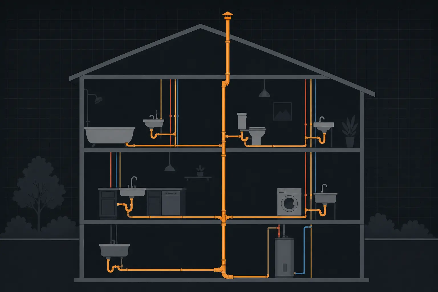
That split is where the money leaks, and it leaks in one specific direction. A floor plan is a horizontal projection. It shows you the route across the building and tells you nothing about the route up and down it. Every riser, every stack, every vent through the roof and every drop from a branch to a fixture rough-in is real pipe that a plan trace silently values at zero. This is the single most-missed quantity in plumbing estimating, and it is missed for a structural reason rather than a careless one.
The Four Phases, In Order
Take the job off in construction sequence, because that is how the risk is stacked:
1. Site utilities and underground - everything below the slab and out to the city connection, plus the trenching, bedding and spoil that goes with it.
2. Above-ground rough-in, sanitary and vent - the gravity systems in the walls, floors and ceilings.
3. Above-ground rough-in, domestic water - the pressurized hot and cold distribution.
4. Finish and trim - the fixtures, trim and specialties that go in at the end.
Underground is first because it is the highest risk portion of the job. It is the part you cannot fix cheaply once the slab is poured, it drags excavation and backfill along with it, and it depends on invert elevations that live on the civil drawings rather than the plumbing ones.
Takeoff and Estimate Are Two Different Documents
The takeoff answers how much. The estimate answers what it costs. Keep them in separate documents. The takeoff becomes your purchase order and your material release schedule; the estimate applies pricing, labor, overhead and profit on top of it. When a job goes sideways you need to know whether you counted wrong or priced wrong, and one blended spreadsheet hides which one it was.
Read the Set and the Fixture Schedule
Plumbing lives in Division 22 of the specifications, and the plumbing drawings are the last place you should start. Read the set in this order before you measure anything.
1. The Fixture Schedule
This is the spine of a plumbing takeoff and it is the one document that makes the count reliable. The schedule lists every fixture by tag - P-1, WC-1, L-1, S-1 and so on - with the manufacturer, model, and the rough-in requirements for each. Take your count off the schedule and then match each scheduled tag to its symbol on the plan. Working in that direction rather than the reverse is what stops a fixture that appears on both the architectural and the plumbing sheets from getting counted twice, and it catches the fixture that is scheduled but never drawn.
Read the model numbers, not just the tags. A wall-hung lavatory and a pedestal lavatory are the same count and completely different rough-in scope. The first one needs a concealed chair carrier in the wall and the second one does not.
2. The Specifications, Division 22
Division 22 sets the wiring of the whole job: pipe material by system, joining method, insulation, valve types, acceptable manufacturers, and testing and disinfection requirements. It is where you learn whether the sanitary is no-hub cast iron or Schedule 40 PVC, and whether the domestic water is copper, PEX or CPVC. That single answer changes your material, your fitting set, your hanger spacing and your install method across most of the job. Where the plans and specifications disagree, the specifications usually control, and you should ask rather than assume.
3. The Riser and Isometric Diagrams
These are the sheets that carry the vertical dimension of the job, and they are the sheets estimators skip. A riser diagram shows the stacks and risers in elevation with sizes and fixture connections. An isometric shows a fixture group in three dimensions. Neither is drawn to scale in a way you can measure with a wheel, but both tell you how many feet of pipe go up and down and at what size. You cannot do an honest plumbing takeoff from floor plans alone, and this is the reason.
4. The Floor Plans
Now you can trace. Plumbing plans are usually split by system: sanitary and vent on one sheet, domestic water on another, sometimes gas and storm on a third. Take them as separate passes, because they are separate networks with separate materials and separate rates.
5. The Civil and Architectural Sheets
Civil gives you the invert elevations at the property line and the point of connection, which set your trench depth and therefore your excavation volume. Architectural gives you finished wall thicknesses, ceiling heights and floor assemblies, which is what lets you convert a riser diagram into real feet. Architectural also gives you the reflected ceiling plans where routing conflicts with ductwork will show up.
6. General Notes and Addenda
Notes carry scope that has no symbol anywhere. A note requiring all domestic water to be insulated, or trenching to be backfilled with imported sand, or the contractor to provide temporary facilities, changes your quantities with no drawing change to warn you. Read them twice, and read every addendum, because an addendum that reschedules fixtures invalidates a count you already finished.
The Scale Trap
Contractors on Contractor Talk list drawing scale mismatches between sheets as one of the top recurring causes of bad takeoffs, alongside scope buried in notes split across plans. Plumbing sheets are frequently reduced or reissued at a different scale than the architectural set they were drawn over. Calibrate your scale on every single sheet against a known dimension, not once per project. A plan that is off by even a small factor produces a pipe quantity that is wrong everywhere at once and looks perfectly reasonable.
Counting Fixtures and What the Count Drives
Each fixture is one count point. One toilet, one lavatory, one sink, one tub, one shower, one water heater, one floor drain. Faucets and trim are not separate counts; they belong to the fixture. Count off the schedule, tick each one on the plan, and keep the tally organized by room rather than by sheet so you can sanity-check the numbers against what a room should plausibly contain.
The reason the fixture count deserves its own pass is that a large share of the material list is derived from it rather than measured. Get the count right and a dozen other quantities fall out automatically. Get it wrong and every one of them is wrong in the same direction.
What the Fixture Count Derives
| Derived item | How it comes off the count | Notes |
|---|---|---|
| P-traps | Fixture count, less water closets, less combination fixtures, less untrapped drains | IPC 1002.1 requires each fixture to be separately trapped. Water closets have an integral trap, so they do not add a trap to your list. |
| Rough-in connections | One set per fixture: hot stub-out, cold stub-out, waste, vent | Varies by fixture type. A toilet has one supply, not two. A floor drain has no supply. |
| Stop valves | One per supply stub-out | Two per lavatory or sink, one per toilet. |
| Chair carriers | One per wall-hung water closet, lavatory or urinal | Concealed in the wall. Easy to miss because the fixture symbol looks identical to a floor-mount. |
| Escutcheons and trim plates | One set per stub-out penetration | Small money, large count. |
| Water heater accessories | Relief valve and discharge piping, expansion control on a closed system, drain pan | IPC 504 and 607.3. The heater is one count; the accessories that legally have to accompany it are four or five more. |
| Hammer arrestors | One per quick-closing valve group | Washing machine boxes and flushometers in particular. |
Fixture Units: The Number That Sizes Everything Downstream
Once you have the count, convert it twice. Drainage fixture units, or DFU, size the gravity system. Water supply fixture units, or WSFU, size the pressure system. These are not cost numbers and they are not flow rates. A fixture unit is a weighting factor chosen so that the load-producing effect of different fixtures can be added together, which is what lets a code table turn a list of fixtures into a pipe size.
You are not the engineer, and on a job with a full design you are not sizing the pipe. But you should run the fixture unit total anyway, for three reasons. It tells you whether the pipe sizes on the plans are plausible. It tells you immediately what a late fixture addition does to the mains. And on design-build or residential work where the drawings are thin, it is the only defensible way to decide what size to bid.
Bathroom Groups Are Not the Sum of Their Parts
Here is the detail that catches people. IPC Table 709.1 assigns a bathroom group with a 1.6 gpf water closet a value of 5 DFU. Add up the same fixtures individually and you get more: a private 1.6 gpf water closet is 3, a lavatory is 1, and a bathtub or a shower at normal flow is 2, for a total of 6. The group value is lower on purpose, because the code recognizes that the fixtures in one bathroom are not all discharging at the same moment.
So which do you use? Use the group value when the fixtures actually form a bathroom group as the code defines it, and add the individual DFU of any extra fixture beyond the group, which is exactly what note f to Table 709.1 tells you to do. Summing everything individually is the conservative error: it oversizes, which is safe for the system and expensive for your bid if you are the one pricing the pipe.
Counting Discipline
Count one fixture type per pass across the whole set rather than counting everything at once on each sheet. Mark each type in a consistent color as you go. It feels slower and it is measurably more accurate, for the same reason that sorting a deck by suit beats sorting it by suit and rank simultaneously. Then reconcile your total against the fixture schedule quantities. If the schedule says eleven and your plan tick marks say ten, you have either found a fixture that was never drawn or missed one that was, and both are worth an RFI while the question is still free.
Measuring Pipe: Developed Length
Pipe is measured by its developed length, and that is not a loose phrase. It is a defined code term. The International Plumbing Code defines developed length in Chapter 2 as the length of a pipe measured along the centerline of the pipe and fittings. The Uniform Plumbing Code and the National Plumbing Code of Canada use the same words.
Four consequences follow directly from that definition, and each one is a mistake people make:
- -Measure along the pipe axis, not along a wall face. The centerline is the line you are measuring, wherever it actually runs.
- -Follow the pipe through every elbow, tee and offset. Never cut a diagonal across a change of direction, and never shorten a run to account for the fitting.
- -Run continuously through walls and floor penetrations. The run does not stop at a wall face and restart on the other side.
- -A fitting is never a deduction. The centerline runs straight through the body of the fitting, so the fitting occupies length rather than removing it. There is no void deduction on a linear pipe run, ever.
Segregate by System, Size, and Material
Every measured pipe line in your takeoff needs three attributes before it means anything: which system, what nominal size, what material. Then a fourth if the spec calls for it: what joining method. So a line item reads "3 inch PVC DWV, solvent weld, above ground" and not "3 inch pipe."
This is not bureaucracy. Hanger spacing is set by material and size. Slope applies to DWV and not to supply. Fitting sets differ completely between a gravity system and a pressure system. And the rate for 1/2 inch is nothing like the rate for 4 inch. A takeoff that does not carry these attributes cannot be priced without guessing, and cannot be re-priced at all when a material substitution comes through in an addendum.
Slope, Fall, and the Length You Actually Get
Drainage piping is sloped, which has two separate effects that people mix up.
The first effect is on length, and it is small. A run sloped at a quarter inch per foot is longer than its horizontal projection by a factor of about 1.0002. That is noise. Do not adjust your lengths for slope.
The second effect is on elevation, and it is not small at all. The cumulative fall is real vertical drop. A hundred feet of 3 inch building drain at the code minimum of an eighth inch per foot drops about 12.5 inches over its run. Two hundred feet of 4 inch drops about 25 inches. That drop has to go somewhere: deeper trench at the far end, a lower point of connection, or a pipe that surfaces above the slab where it cannot. On a long building or a flat site this is the number that turns into an excavation change order, and it is arithmetic you can do in thirty seconds during the takeoff rather than discovering in the field.
Slope minimums come from IPC Table 704.1: a quarter inch per foot for pipe 2.5 inches and smaller, an eighth inch per foot for 3 to 6 inch, a sixteenth inch per foot for 8 inch and larger. Anything upstream of a grease interceptor is a quarter inch per foot regardless of size.
Net Length Versus Ordering Length
The same pipe run yields two different numbers depending on what you are going to do with it, and conflating them is a quiet source of error.
- -Net measured developed length is what goes in a bid and what goes in a progress billing. Waste lives in the unit rate, not in the quantity. This is what the international measurement standards require: RICS NRM2 and POMI both measure work net as fixed in position.
- -Ordering quantity adds scrap, offcuts, damaged stock and the round-up to stock lengths. This is what goes on the purchase order.
Decide which one a given column of your takeoff is, label it, and do not let the two meet. The most common version of this mistake is adding a waste factor to a bid quantity that was already priced with waste in the rate, which quietly pads the bid and loses the job for no reason.
(Pulling those quantities off the PDF sheets is the part Tectonic automates - it reads the drawings and returns the material quantities with your overhead and profit markup applied - but trace one full system by hand before you trust any tool with it, including this one. The manual pass is what teaches you what a missing riser looks like in a total.)
The Vertical Feet Everyone Misses
This is the section that matters most, so here is the claim plainly: on a multi-story job the vertical pipe is routinely the largest single omission in a plumbing takeoff, and a floor-plan trace cannot find it. Not because estimators are careless, but because a floor plan is a horizontal projection. Vertical pipe appears on it as a dot.
Developed length runs up each riser and back down again. Four categories of vertical pipe belong in your quantities:
- -Supply risers - the hot and cold mains going up through the building to serve each floor.
- -Drain and waste stacks - the vertical gravity pipe collecting the horizontal branches.
- -Vent stacks and vents through roof - all the way up and through, plus the code-required height above the roof surface.
- -Fixture drops and rises - the short leg from each horizontal branch down or up to each fixture rough-in. Individually trivial, collectively large, because you have one for every fixture on the job.
How to Actually Get the Number
Read it off the riser or isometric diagram, then build it from the architectural section. You need three inputs: floor-to-floor heights, the depth of the floor assembly, and the roof height above the top plate.
Work one stack at a time and write the arithmetic down:
- -Base of the stack at the building drain to the first floor level
- -First floor to second floor, which is floor-to-floor, not ceiling height
- -Second floor to the ceiling or top plate
- -Top plate through the attic or roof assembly to the roof deck
- -Roof deck to the termination height above the roof surface
Sum it, then multiply by the number of identical stacks. In a repetitive building - apartments, hotels, a row of identical restrooms - this is the highest-leverage twenty minutes in the whole takeoff, because a single stack error multiplies by the stack count.
The Fixture Drop Arithmetic
Fixture drops are the sneaky half. Every lavatory has a tailpiece, a trap arm and a drop to the branch. Every wall-mounted shower valve has a rise from the branch. Every toilet has a closet bend and a short run of 3 inch. Call it a few feet each and it looks like nothing. Multiply by the fixture count and it is not nothing.
Take one representative fixture group, measure its drops honestly off the isometric, and derive a per-fixture average by fixture type. Then apply it by count. That is defensible, it is fast, and it is auditable, which a round guess is not. And the number is yours, from this job, at these ceiling heights, rather than something remembered from a different building.
The Verification Step
Here is the cheapest check in plumbing estimating. Take your total DWV footage and divide it by your total fixture count. On normal residential and light commercial work that ratio lands in a fairly narrow band once you have a few jobs of history, because fixtures come with a fairly consistent amount of pipe attached to them. If this job comes out well below your usual ratio, you have almost certainly missed vertical pipe. The ratio will not tell you where. It will reliably tell you that you need to look, which is most of the value.
Do the same for supply footage per fixture. Two ratios, thirty seconds, and it catches the category of error that a careful second pass through the floor plans structurally cannot.
Fittings, Hangers, and Waste
Once the pipe is measured, three families of quantity come off it: fittings, supports, and the waste allowance. Each one has a standard method and a standard way to get it wrong.
Fittings: Pick Exactly One Method
There are three mutually exclusive ways to account for fittings. Using two of them double counts, and double-counted fittings are a real way to lose a bid you should have won.
| Method | How it works | Where it is standard |
|---|---|---|
| Count each piece | Every fitting, valve and specialty enumerated by size and type. Pipe measured separately. | Standard United States bid practice. This is the component approach in the Mechanical Contractors Association of America labor estimating manual. |
| Percentage uplift | Add a percentage of developed length instead of enumerating the fittings. | Rapid and conceptual estimating only. See the caution below. |
| Deemed included | Fittings to small pipe are included in the measured running length and not counted at all. | International bills of quantities. POMI deems fittings to pipe of 60 mm internal diameter or under included, with larger fittings measured extra over. RICS NRM2 work section 38 does the same unless fittings are separately measured. |
For a hard-money bid on a dense commercial job, count the pieces. Sanitary drainage fittings are where the labor is: combo wyes, long sweeps, closet bends and reducing tees are not interchangeable with a foot of straight pipe, and a bathroom core is mostly fittings with some pipe between them.
A Caution on the Percentage Numbers You Will See
You will run into a widely repeated shortcut that says to add roughly 50 percent of developed length for copper and plastic and roughly 75 percent for standard threaded steel. It is worth knowing where those figures come from, because it is not where people think.
Those percentages originate as an equivalent length allowance for friction loss in water pipe sizing. IPC Appendix E, which covers sizing of the water piping system, handles fittings by "converting to equivalent length of piping and adding to the total pipe length" so that pressure loss through the fittings can be computed. That is a hydraulic calculation whose output is a pipe diameter. It is not a material quantity and it was never intended as one.
Using a friction-loss allowance as a fitting cost allowance is not automatically wrong by a factor that matters, but it is unsourced when you do it, and it will not track the actual fitting density of the job in front of you. A stadium restroom core and a warehouse with a single hose bibb do not have the same fittings per foot, and a flat percentage cannot tell them apart. If you use a percentage uplift, calibrate it from your own completed jobs, label it as your number, and stop citing code for it.
Hangers and Supports Are Derived, Not Counted
Do not try to count hangers off a plan. Compute them. The count is developed length divided by the code maximum spacing for that material and size, rounded up, plus extras at every riser, direction change and piece of equipment.
Spacing comes from IPC Table 308.5, mirrored in IRC Table P2605.1. The values that drive most jobs:
| Material and size | Max horizontal spacing | Max vertical spacing |
|---|---|---|
| PVC pipe | 4 ft | 10 ft |
| ABS pipe | 4 ft | 10 ft |
| Cast-iron pipe | 5 ft | 15 ft |
| Copper or copper-alloy tubing, 1-1/4 in and smaller | 6 ft | 10 ft |
| Copper or copper-alloy tubing, 1-1/2 in and larger | 10 ft | 10 ft |
| Copper or copper-alloy pipe | 12 ft | 10 ft |
| CPVC, 1 in and smaller | 3 ft | 10 ft |
| CPVC, 1-1/4 in and larger | 4 ft | 10 ft |
| PEX, 1 in and smaller | 32 in | 10 ft |
| PEX, 1-1/4 in and larger | 4 ft | 10 ft |
| Steel pipe | 12 ft | 15 ft |
Three notes on that table that change quantities:
- -Cast iron horizontal spacing increases to 10 feet where 10-foot pipe lengths are installed, which is a genuine material saving if the spec allows the longer lengths. Separately, cast iron must be supported at every joint, meaning a support at every bell on hub-and-spigot and at every coupling on no-hub. On a job with short pieces those two rules fight each other, and the joint rule wins.
- -PEX at 32 inches is the outlier that wrecks estimates. It needs roughly twice the supports of copper tubing at the same size and more than four times steel. Switching a spec from copper to PEX cuts pipe cost and raises support count sharply, and an estimator who carries forward a copper hanger count after a PEX substitution is materially short.
- -For sizes 2 inches and smaller, a guide is required midway between the required vertical supports. That is an extra piece of hardware per interval that most takeoffs never list.
All vertical runs, regardless of material, must be supported at each floor level. Riser clamps are the standard support for vertical cast iron.
Waste and Scrap
Waste on pipe is about offcuts and stock-length round-up rather than breakage, so it behaves differently by system. Long straight runs in large-diameter pipe waste very little. Cut-up routing in small-diameter pipe wastes a lot, because a two-foot remnant has nowhere to go.
As standard practice, roughly five to ten percent on pipe is the normal range, trending to the high end on tight residential rough-in and the low end on long straight commercial mains. Small fittings, straps and hangers are worth ordering roughly ten percent over the computed count because they get dropped, cracked and lost. Fixtures are the exception: order the exact counted number. Nobody loses a toilet.
And remember which column you are in. Those allowances belong in a procurement quantity, not in a bid quantity that already carries waste in the rate.
Worked Example: A Three-Bath House
Here is a full takeoff on a small job, with the arithmetic shown. Two-story single family, three bathrooms, slab on grade at the first floor, Schedule 40 PVC for DWV, PEX for domestic water. Quantities below are measured off the plans and riser diagram for this hypothetical house; the code values are from the tables cited.
Step 1: Fixture Count Off the Schedule
| Tag | Fixture | Qty |
|---|---|---|
| WC-1 | Water closet, private, 1.6 gpf | 3 |
| L-1 | Lavatory | 3 |
| BT-1 | Bathtub with shower | 1 |
| SH-1 | Shower, under 5.7 gpm | 2 |
| KS-1 | Kitchen sink with disposer and dishwasher | 1 |
| DW-1 | Dishwasher, domestic | 1 |
| CW-1 | Clothes washer, residential | 1 |
| LT-1 | Laundry tray | 1 |
| FD-1 | Floor drain, garage | 1 |
| HB-1 | Hose bibb | 2 |
| WH-1 | Water heater | 1 |
Fourteen drainage fixtures, seventeen counts including the hose bibbs and the heater.
Step 2: DFU Total, Both Ways
Individually, from IPC Table 709.1: three water closets at 3 is 9, three lavatories at 1 is 3, the tub at 2, two showers at 2 is 4, kitchen sink 2, dishwasher 2, clothes washer 2, laundry tray 2, floor drain 2. Total 28 DFU.
By bathroom group, which is the correct method here because the fixtures do form three groups: three groups at 5 DFU is 15, plus kitchen sink 2, dishwasher 2, clothes washer 2, laundry tray 2, floor drain 2. Total 25 DFU.
The 3 DFU difference is the group allowance doing its job. Carry 25.
Step 3: Size Check Against the Tables
Building drain, from IPC Table 710.1(1): 3 inch pipe at a quarter inch per foot carries 42 DFU, so 25 DFU fits, and note a to that table requires any building drain serving a water closet to be at least 3 inch anyway. A 4 inch building drain at an eighth inch per foot carries 180 DFU, which is what most builders and many local amendments will actually want here. Bid what the plans and the local code say; the point of the check is that a 3 inch line would not have been a code violation on capacity, so if the plans show 4 inch you know it is for jurisdiction or preference rather than load.
Main stack, from IPC Table 710.1(2): the two upstairs bathroom groups put 10 DFU on it, and a 3 inch stack of three branch intervals or less carries 48. Comfortable.
Water supply, from UPC Appendix B Table B.5.2 at individual-dwelling values: three tank-type water closets at 2.5 is 7.5, three lavatories at 1.0 is 3.0, tub and shower combination 4.0, two showers at 2.0 is 4.0, kitchen sink 1.5, dishwasher 1.5, clothes washer 4.0, laundry sink 2.0, first hose bibb 2.5 plus one additional at 1.0. Total 31 WSFU.
Step 4: Horizontal Pipe, Measured
| System | Size | Horizontal LF |
|---|---|---|
| DWV below slab and sewer | 4 in | 110 |
| DWV above ground | 3 in | 96 |
| DWV above ground | 2 in | 124 |
| DWV above ground | 1-1/2 in | 88 |
| Domestic water trunk | 3/4 in | 145 |
| Domestic water branches | 1/2 in | 310 |
Step 5: Vertical Pipe, From the Riser Diagram
Floor-to-floor is 10 feet. Second floor to top plate is 9 feet. Top plate to roof deck averages 5 feet.
- -Main 3 inch stack, building drain to vent through roof: 10 + 9 + 5 = 24 LF, plus 1 LF above the roof surface = 25 LF
- -Secondary 2 inch stack serving kitchen and laundry: 10 + 9 + 5 + 1 = 25 LF
- -Two 3/4 inch supply risers, first floor to second floor ceiling: 2 x 19 = 38 LF
- -Fixture drops and rises, measured off one representative bath isometric and applied by count: 14 drainage fixtures at an average 4 LF = 56 LF, and 13 supply stub-out groups, meaning the wall and floor locations needing a hot and cold pair, at an average 3 LF of 1/2 inch = 39 LF
Add it up: 106 LF of DWV and 77 LF of domestic water that no floor plan shows. Against 418 LF of horizontal DWV that is a 25 percent addition, and against 455 LF of horizontal supply it is 17 percent. On a two-story house with one stack. Scale that thought to a four-story building with eight stacks and the omission stops being a rounding error.
Step 6: The Verification Ratio
Total DWV is 418 horizontal plus 106 vertical, or 524 LF, over 14 drainage fixtures. That is 37 LF of DWV per fixture. Total supply is 455 plus 77, or 532 LF, over 16 supply points, so 33 LF per point. Write both ratios on the takeoff. On the next house of this size and layout they are your first sanity check, and the version of this job without the vertical pipe would have read 30 LF per fixture, which is the kind of gap you can actually notice.
Step 7: Derived Quantities
- -Traps: 14 drainage fixtures less 3 water closets with integral traps, less the dishwasher which discharges through the sink, and the floor drain trap is integral to the drain body. Call it 9 P-traps.
- -Hangers, above-ground PVC: 308 LF of 3 inch, 2 inch and 1-1/2 inch above-ground DWV divided by the 4 foot maximum for PVC is 77, plus roughly 15 extras at direction changes and stack bases, so 92.
- -Hangers, PEX: 455 LF of horizontal 1/2 inch and 3/4 inch, both in the 1 inch and smaller band, divided by 32 inches is 171. Round up and add extras at the manifold and drops for about 190. Note that the same footage in copper tubing at 6 foot spacing would have been 76. The PEX support count is two and a half times higher for the same pipe.
- -Cleanouts: the 110 LF of 4 inch below slab and sewer needs at least two on the 100 foot interval rule, one at the building drain to building sewer junction per IPC 708.1.3, one at the base of each of the two stacks, and one at each change of horizontal direction greater than 45 degrees, of which this plan has four, though two fall within 40 feet of developed length of each other and share one under IPC 708.1.4. That totals 8 cleanouts, each sized to the pipe it serves.
- -Stop valves: two per lavatory and sink, one per toilet, plus washer box and dishwasher. 16.
- -Water heater accessories: relief valve, discharge piping, expansion tank, drain pan and pan drain. 5 line items off one fixture count.
Every one of those derived numbers traces to a count or a length you can point at. That is the property that makes a takeoff defensible in a scope review, and it is worth more than precision to the last foot.
Reference Tables and What Gets Missed
Keep these where you can reach them during a takeoff. All values are from the code sections named; verify against the edition your jurisdiction has actually adopted, because amendments are common in plumbing and sometimes severe.
Drainage Fixture Units, IPC Table 709.1
| Fixture | DFU | Min trap size |
|---|---|---|
| Bathroom group, 1.6 gpf water closet | 5 | - |
| Bathroom group, water closet over 1.6 gpf | 6 | - |
| Water closet, private, 1.6 gpf | 3 | Note d |
| Water closet, public, 1.6 gpf | 4 | Note d |
| Water closet, public, over 1.6 gpf | 6 | Note d |
| Lavatory | 1 | 1-1/4 in |
| Bathtub, with or without shower | 2 | 1-1/2 in |
| Shower, 5.7 gpm or less | 2 | 1-1/2 in |
| Shower, over 5.7 to 12.3 gpm | 3 | 2 in |
| Shower, over 12.3 to 25.8 gpm | 5 | 3 in |
| Kitchen sink, domestic | 2 | 1-1/2 in |
| Dishwashing machine, domestic | 2 | 1-1/2 in |
| Laundry tray, 1 or 2 compartments | 2 | 1-1/2 in |
| Clothes washer, residential | 2 | 2 in |
| Clothes washer, commercial | 3 | 2 in |
| Service sink | 2 | 1-1/2 in |
| Floor drain | 2 | 2 in |
| Emergency floor drain | 0 | 2 in |
| Drinking fountain | 1/2 | 1-1/4 in |
| Urinal | 4 | Note d |
| Urinal, 1 gpf or less | 2 | Note d |
A showerhead over a bathtub does not increase the tub's DFU value. Fixtures not listed take a value by trap size under Table 709.2: 1-1/4 in is 1, 1-1/2 in is 2, 2 in is 3, 2-1/2 in is 4, 3 in is 5, 4 in is 6. Where you only know a flow rate, IPC 709.3 converts at 1 gpm equals 2 DFU.
Minimum Drain Slope, IPC Table 704.1
| Pipe size | Minimum slope |
|---|---|
| 2-1/2 in or less | 1/4 in per ft |
| 3 in to 6 in | 1/8 in per ft |
| 8 in or larger | 1/16 in per ft |
Piping upstream of a grease interceptor is 1/4 in per ft regardless of size.
Maximum DFU on Building Drains and Sewers, IPC Table 710.1(1)
| Pipe size | At 1/8 in/ft | At 1/4 in/ft |
|---|---|---|
| 2 in | - | 21 |
| 3 in | 36 | 42 |
| 4 in | 180 | 216 |
| 6 in | 700 | 840 |
Any building drain serving a water closet is a minimum of 3 inch.
Maximum DFU on Branches and Stacks, IPC Table 710.1(2)
| Pipe size | Horizontal branch | Stack, 3 intervals or less | Stack, over 3 intervals |
|---|---|---|---|
| 1-1/2 in | 3 | 4 | 8 |
| 2 in | 6 | 10 | 24 |
| 3 in | 20 | 48 | 72 |
| 4 in | 160 | 240 | 500 |
| 6 in | 620 | 960 | 1,900 |
Maximum Trap Arm Length, IRC Table P3105.1
| Trap size | Slope | Max distance trap to vent |
|---|---|---|
| 1-1/4 in | 1/4 in/ft | 5 ft |
| 1-1/2 in | 1/4 in/ft | 6 ft |
| 2 in | 1/4 in/ft | 8 ft |
| 3 in | 1/8 in/ft | 12 ft |
| 4 in | 1/8 in/ft | 16 ft |
Self-siphoning fixtures such as water closets are not limited. Total fall in a fixture drain must not exceed one pipe diameter, and no vent may be installed within two pipe diameters of the trap weir.
Wet Vent Size, IRC Table P3108.3
| Wet vent size | Max DFU load |
|---|---|
| 1-1/2 in | 1 |
| 2 in | 4 |
| 2-1/2 in | 6 |
| 3 in | 12 |
| 4 in | 32 |
Any combination of fixtures within two bathroom groups on the same floor level may be vented by a horizontal wet vent, and not more than one wet-vented fixture drain may discharge upstream of the dry-vented fixture drain connection. Wet venting is worth understanding at takeoff time because it removes vent pipe and fittings from the job compared with individually venting everything, and a plan drawn one way priced the other way is money on the table in whichever direction you got it wrong.
Standard Rough-In Dimensions, Approximate Trade Practice
These are conventions, not code, and they are always subordinate to the manufacturer rough-in sheet for the specified model:
- -Water closet: 12 in from the finished wall to the center of the closet flange, with 10 in and 14 in models also made
- -Water closet supply stub-out: roughly 6 to 8 in above the floor, offset left of center
- -Lavatory drain: roughly 17 to 19 in above the floor
- -Stub-out projection: always account for the finished wall thickness, drywall plus backer board plus tile, or the trim will not reach
The Scope That Gets Missed
Work this list before you call a plumbing takeoff finished:
- -Vertical pipe. Risers, stacks, vents through roof, fixture drops. Covered above at length because it is the big one.
- -Slab penetrations and sleeves. Every pipe coming up through concrete needs a sleeve set before the pour. Miss them and you are paying for coring later.
- -Excavation, bedding and spoil haul-off for the underground portion. Length times width times depth divided by 27 gives cubic yards, and a deep trench that has to be sloped or shielded moves far more dirt than its nominal section suggests.
- -Chair carriers for every wall-hung fixture.
- -Cleanouts at the base of every stack, at the building drain to sewer junction, and at every change of direction over 45 degrees, not just on the 100 foot interval.
- -Cumulative fall on long drain runs, and what it does to your trench depth at the far end.
- -Testing, flushing and disinfection as enumerated closeout scope. IPC 312 covers pressure and air testing; IPC 610 with AWWA C651 covers potable system disinfection. It is specified work with real cost and it appears in no fixture count.
- -Pipe insulation where the spec calls for it, measured by length over the pipe.
- -Equipment connections on other trades' drawings. Mechanical equipment with condensate drains, kitchen equipment with indirect wastes, and anything on the mechanical or kitchen schedules that needs water or drain. Take one deliberate pass through the mechanical, kitchen and architectural sheets looking only for things that need a pipe.
- -Hose bibbs, floor drains and mop sinks, which are chronically left off because they are not in a bathroom group and nobody thinks of them as fixtures.
(A takeoff tool that pulls quantities off the sheet will find the things that are drawn. It will not find scope that exists only in a general note or on the mechanical schedule, which is why the checklist above stays a human step no matter what you are estimating with.)
One Last Habit
Contractors on both Plumbing Zone and Contractor Talk keep landing on the same conclusion about tooling, and it is worth repeating because it applies to hand takeoffs, spreadsheets, digitizers and AI alike. As one estimator put it in a thread on takeoff accuracy, even the best takeoff tools are only as good as the person operating them, and a manual spot check on key quantities is not optional. Another was blunter: whether it is by hand or by computer, it still needs to be reviewed and verified. Pick two or three quantities that carry the most dollars on every job - on plumbing that is usually the underground, the stacks and the fixture count - and check those by hand every time, no matter where the numbers came from.
Key Takeaways
- 1.A plumbing takeoff is several parallel networks measured side by side and never merged: supply piping sized by water supply fixture units, DWV sized by drainage fixture units, vent as its own system, plus storm and gas where they are in scope.
- 2.Developed length is a defined code term, the length of a pipe measured along the centerline of the pipe and fittings per IPC Chapter 2, which means a fitting occupies length and is never deducted from a pipe run.
- 3.Vertical pipe is the largest routine omission in plumbing estimating because a floor plan is a horizontal projection; risers, stacks, vents through roof and fixture drops have to be read off the riser or isometric diagram.
- 4.IPC Table 709.1 rates a bathroom group with a 1.6 gpf water closet at 5 DFU, which is deliberately less than the 6 DFU you get adding the same water closet, lavatory and tub individually, because the code assumes they do not all discharge at once.
- 5.The 50 percent and 75 percent fitting allowances that circulate in estimating originate as equivalent-length friction-loss allowances for water pipe sizing in IPC Appendix E, not as material cost allowances, so calibrate any percentage uplift from your own completed jobs instead of citing code for it.
- 6.PEX 1 inch and smaller requires support every 32 inches under IPC Table 308.5 against 6 feet for copper tubing of the same size, so a copper-to-PEX substitution roughly doubles the support count on identical footage.