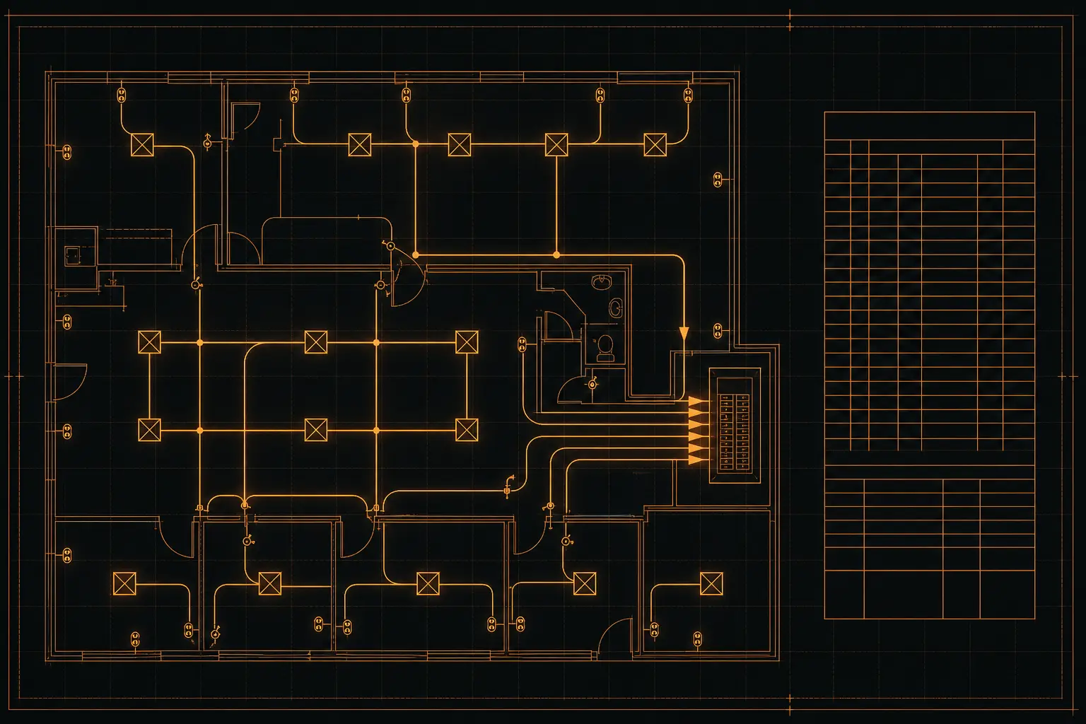
01How to Do an Electrical Takeoff
An electrical takeoff is a complete count of every device, fixture, box, foot of wire, foot of conduit, breaker and piece of gear the job needs. You produce it in four passes: count the devices and fixtures one symbol type at a time, work out the branch circuits and homeruns from the panel schedules, measure or calculate the wire and conduit that connects all of it, then list the distribution equipment off the one-line diagram. Everything else in electrical estimating is pricing what those four passes produced.
The thing that makes electrical harder than the other trades is that it is two different kinds of takeoff stapled together. Drywall is area. Roofing is area plus perimeter. Electrical is count plus length, and the two halves behave differently: the count comes straight off the symbols, but the length has to be inferred from a route nobody drew to scale. That split is where the money leaks. An estimator can count 312 receptacles perfectly and still be twenty percent light on the bid because the wire behind those receptacles was figured at fifteen feet a device when the job ran eighteen.
The Four Passes
- -Devices and fixtures - receptacles, switches, data drops, light fixtures, exit signs, sensors, disconnects, floor boxes. Pure counting off the legend.
- -Circuits and homeruns - how many branch circuits, how many breakers, how many homerun runs back to each panel. Read off the panel schedules and the homerun arrows.
- -Wire and conduit - linear feet by type and size, conductors by gauge and insulation, plus the fittings, straps, couplings and boxes that ride along with them.
- -Gear - panels, switchboards, transformers, disconnects, starters, transfer switches. Low count, high dollar, long lead.
Keep those four on separate sheets. An estimator who blends them into one price per square foot loses the ability to bid an unusual job, because device density does not scale with floor area. Two 8,000 SF spaces can carry wildly different electrical scope: an open warehouse with high bay fixtures and a handful of equipment circuits, and a medical office with dense receptacles, isolated grounds, data at every wall, and a lighting control system. A blended square foot number underbids the second one every single time.
Takeoff and Estimate Are Two Different Documents
The takeoff answers how much. The estimate answers how much it costs. The takeoff produces quantities and becomes your purchase order and your material release schedule; the estimate applies material pricing, labor, overhead and profit to those quantities. Keep them apart. When a job goes wrong you need to know whether you counted wrong or priced wrong, and a single blended spreadsheet hides which one it was.
Where the Dollars Actually Are
It is worth knowing which half of your takeoff carries the risk before you start. Estimating 101, in its guidance on commercial branch wiring, puts branch wiring at roughly 60 to 80 percent of the estimate on most commercial projects, and only 5 to 10 percent on industrial work where the gear dominates. That is the single most useful orientation fact in electrical estimating: on a normal commercial job, the pipe and wire feeding the devices is most of your number, and the switchgear everyone worries about is not. Spend your review time accordingly.
02Read the Set in Order
Electrical drawing sets follow a predictable order, and reading them out of order is how scope gets missed. Work front to back before you count anything.
1. The Symbol Legend
This is the decoder ring, and it is job-specific. A filled triangle means one thing on this job and something else on the next. Read every line of the legend and write down the symbols that are unusual: isolated ground receptacles, controlled receptacles, floor boxes, quad outlets, keyed switches, emergency fixtures. Any symbol on the legend you cannot find on a plan sheet is a question, and any symbol on a plan sheet that is not on the legend is a bigger one.
2. General Notes
The notes carry requirements that have no symbol at all. A single note saying all conduit in finished areas shall be concealed, or all devices shall be specification grade, or the contractor shall provide temporary power for the duration, changes your quantities and your price with no drawing change to warn you. Read them twice.
3. The Specifications, Division 26
Division 26 sets wiring method, conduit type, wire type, device grade, acceptable manufacturers, and testing requirements. It is where you learn whether the branch wiring is EMT and THHN or MC cable, and that single answer can swing the material and the install method for most of the job. When plans and specifications disagree, the specifications usually control, and you should ask rather than assume.
4. Power, Lighting, and Systems Plans
Power plans give you receptacles, equipment connections and panel locations. Lighting plans give you fixtures, switching and controls. Systems plans give you fire alarm, data, security and access control. Take them as separate passes, because they are separate scopes with separate pricing.
5. The One-Line Diagram
The one-line is the map of power flow from the utility through the service to every panel. It is the only place some feeders appear. Measuring conduit from the floor plans and never opening the one-line is one of the most expensive omissions in the trade, because feeders are large conduit and large conductor and they cost real money per foot.
6. Panel Schedules
Every circuit, every breaker, every load. The panel schedule is both a source of quantities and the best cross-check you have on your own device count. More on that below.
7. Details and Risers
Risers give you vertical runs, which do not appear in plan view at all. A three-story building has feeder and branch rise between floors that is invisible on any floor plan. If you only measured horizontally, you are short by the height of the building times the number of runs.
Check the Revisions Before You Count
Confirm you have the current revision of every sheet, and read every addendum. Revision clouds mark scope that changed after the original issue. Counting off a superseded sheet produces a takeoff for a building nobody is going to build, and the error is silent because your arithmetic will be perfect.
03Counting Devices Without Missing Any
Counting is the easy part of electrical takeoff and the part most often done badly, because there are hundreds of small symbols and human attention degrades across a forty sheet set.
Count One Symbol Type Per Pass
Do not walk a sheet counting everything at once. Count every duplex receptacle across the whole set, then start over and count every GFCI, then every switch, then every 3-way. One symbol type per pass is faster, and more importantly it is verifiable: you can recount a single symbol type in a few minutes when a number looks wrong, which you can never do with a mixed count.
Mark each symbol as you count it, with a consistent color per type, and use the same colors on every job. The point of the color discipline is not neatness. It is that a sheet with an unmarked symbol on it is visibly wrong from three feet away.
Count by Room, Not by Sheet
Organize the count sheet by room or by area rather than by drawing sheet. Room-based counts can be sanity-checked against reality, because you know roughly what a private office or a patient room or a classroom contains. A column of sheet totals cannot be checked against anything.
The Standard Device Categories
- -Receptacles - duplex, GFCI, quad, isolated ground, controlled, USB, weather resistant, tamper resistant, and the higher amperage configurations for specific equipment
- -Switches - single pole, 3-way, 4-way, dimmer, keyed, timer, occupancy and vacancy sensors
- -Lighting - each fixture type by its schedule tag, plus exit signs and emergency units counted separately
- -Low voltage - data and voice jacks, fire alarm devices, access control, security, AV
- -Equipment connections - disconnects, motor starters, drives, hard-wired appliance connections
- -Boxes - device boxes, fixture boxes, junction boxes, pull boxes, floor boxes
Use the Schedules as the Count
For lighting, do not count fixture symbols and stop there. The lighting fixture schedule lists every type with its manufacturer, catalog number, lamp, voltage and mounting. Count the symbols by tag, then reconcile against the schedule: a fixture type that appears in the schedule but has no symbols on any plan is either a missing sheet or a deleted scope, and either way it is a question for the engineer before bid day, not a discovery at rough-in.
The Code Rules That Set Residential Counts
On residential work you are frequently counting against code minimums rather than a fully drawn plan, and the relevant NEC sections tell you what has to be there. Under NEC 210.52(A)(1), receptacles must be placed so that no point along the floor line of any wall space is more than 6 feet from a receptacle, which is where the trade shorthand of a receptacle every 12 feet comes from. The code language is the 6 foot reach, not the 12 foot spacing, and on a wall with a door in the middle those are different answers. NEC 210.52(A)(2) defines wall space as any space 2 feet or more in width unbroken along the floor line, so a 22 inch strip of wall between two doors does not require an outlet and a 26 inch strip does.
Kitchens run on their own rules. NEC 210.52(C)(1) requires a receptacle at each countertop or work surface 12 inches or wider, spaced so no point along the countertop wall line is more than 24 inches from a receptacle. Those countertop receptacles do not count toward the general wall space requirement of 210.52(A), which means a kitchen wall can need both. Bathrooms need at least one receptacle within 3 feet of the outside edge of each basin under 210.52(D).
Also worth knowing for the count: under 210.52, receptacles do not count toward the required outlets if they are part of a luminaire or appliance, inside a cabinet or cupboard, controlled by a wall switch under the 210.70(A)(1) exception, or more than 5.5 feet above the floor. Floor receptacles only count if they are within 18 inches of the wall.
What Gets Missed in the Count
The misses are consistent across every estimator who has ever done this:
- -Exterior receptacles and lighting, because they live on a different sheet
- -Mechanical and electrical room convenience outlets, which are often noted rather than drawn
- -Roof receptacles at equipment, required for servicing
- -Equipment connections shown only on the mechanical or plumbing drawings, never on the electrical
- -Owner-furnished equipment that still needs a contractor-installed circuit and disconnect
- -Devices in millwork and casework, shown only in the architectural details
- -Fire alarm devices, when the fire alarm is drawn as a performance spec rather than a device layout
The habit that catches most of these: after you finish the electrical sheets, take one deliberate pass through the architectural, mechanical and plumbing drawings looking only for things that need power. Every piece of mechanical equipment on the mechanical schedule needs a circuit, a disconnect and a connection, and about a third of the time it is not shown on the electrical plans at all.
04Circuits, Homeruns, and the Panel Schedule
A branch circuit is everything downstream of its breaker. A homerun is the specific leg from the panel to the first device or junction point on that circuit. The NEC never uses the word homerun, but every plan you will ever read shows them: an arrowhead on a circuit line pointing back toward the panel, with the panel designation and circuit number written beside it, and slash marks across the line indicating conductor count.
Every homerun arrow is a discrete line item. It is a length of conduit, a set of conductors, and a breaker. Counting the arrows gives you a number you can check against the panel schedule, and that cross-check is the single most valuable verification step in an electrical takeoff.
The Panel Schedule Is Your Audit
Count the circuits shown in each panel schedule. Then count the homerun arrows on the plans that point to that panel. Those two numbers should reconcile. When they do not, you have found something real before bid day rather than after: a circuit on the schedule with no homerun on the plan means scope drawn nowhere, and a homerun on the plan with no circuit on the schedule means the schedule is stale. Either way it is an RFI, and an RFI you send during bidding is free while the same discovery during rough-in is a change order argument you may lose.
The panel schedule also hands you your breaker count directly, broken out by type and trip rating, including the AFCI and GFCI breakers that cost several times what a standard breaker costs. Take the breakers off the schedule, not off an assumption.
How Many Devices Go on a Circuit
This is one of the most commonly misstated facts in the trade, and the answer is different for residential and commercial.
For dwellings, the NEC sets no maximum number of receptacles on a general-purpose 15A or 20A branch circuit. None. The load calculation runs off Table 220.12, which assigns a general lighting load of 3 VA per square foot for dwelling units and covers the general-purpose receptacles within that. The commonly quoted figures of 8, 10 or 12 receptacles per 20A circuit are trade convention and design practice, not code. They are reasonable conventions and you can estimate with them, but you should know you are using a convention so you can adjust it when the drawings or the local amendments say otherwise.
For non-dwellings, there is a real number and it comes out of the load calculation. NEC 220.14(I) assigns 180 VA to each receptacle outlet in non-dwelling occupancies, where a single, duplex, or multiple receptacle on one yoke all count as one outlet. A 20A 120V circuit carries 2,400 VA, and 2,400 divided by 180 is 13.3, which is why 13 duplex receptacles per 20A commercial circuit is the standard estimating figure. Some designers work to 10 or 12 for margin, which is again convention layered on top of the code number.
The Circuits Code Requires Regardless
On residential work several circuits are mandatory and are easy to leave off a count built purely from symbols:
- -Two or more 20A small-appliance branch circuits serving kitchen, pantry, breakfast room and dining room [210.11(C)(1)]
- -At least one 20A laundry circuit with no other outlets on it [210.11(C)(2)]
- -At least one 20A bathroom receptacle circuit [210.11(C)(3)]
Those are minimums before you count a single dedicated appliance circuit for the range, dryer, dishwasher, disposal, microwave, HVAC equipment or water heater.
The 80 Percent Rule
Any load expected to run for three hours or more is a continuous load, and NEC 210.19(A)(1) and 210.20(A) require the conductors and the overcurrent device to be sized at 125 percent of it. Run the arithmetic the other direction and it is the familiar 80 percent rule: a 20A circuit carries a maximum of 16A of continuous load. This matters at takeoff time because it is what forces an extra circuit onto a lighting run or a bank of equipment, and an extra circuit is an extra breaker, an extra homerun, and more pipe and wire.
Combined Homeruns
On commercial work, several circuits routinely share a single homerun conduit back to the panel. Four circuits in one pipe is common. This is a quantity decision with real consequences: combining reduces conduit footage and increases conductor count in that pipe, and it changes the conduit size you need to satisfy fill. Decide your convention before you start measuring and apply it consistently, because the wire calculation in the next section depends entirely on knowing how many conductors are in an average foot of your branch pipe.
05Wire and Conduit: The Part That Moves the Number
This is where electrical bids are won and lost. On a commercial job the branch wiring is most of the estimate, and it is the only major quantity on the entire takeoff that is not drawn to scale anywhere in the set. You are inferring it.
The Average Foot Per Device Method
The standard approach is to establish an average length of branch run per device and multiply by the device count. It is a legitimate method used by working estimators, and it is fast. It is also the single largest error source in the trade, for a reason worth stating plainly.
Estimating 101 puts the danger in arithmetic that is hard to argue with: if you use an average of 15 feet per device and the real average on that job was 18 feet, you are 20 percent short on the branch wiring. Since branch wiring is roughly 60 to 80 percent of a commercial estimate, a three foot error in an average you picked casually just moved your whole bid by twelve to sixteen percent, in the wrong direction, on the single largest cost category in the job. Their advice is the right advice: do not use the same averages for all types of projects.
The way to use the method safely is to derive the average from the job in front of you rather than from memory. Measure ten or fifteen actual runs across representative areas of the plan, from device to device and from the last device back to the panel. Average those. Use that number for the rest. It takes twenty minutes and it converts a guess into a measurement.
Electricians have used the same trick on the install side for decades. On the Mike Holt forums, one estimator described sizing hotel low-voltage cable by measuring the longest room pull and the shortest, averaging the two, and multiplying out across the rooms and floors. Crude, fast, and close enough for cable he could reorder; he reported waste running three to four percent. The same poster drew the correct line around it: for large feeders you measure precisely, because being wrong on 750 MCM is not a rounding error.
Getting the Length Right on Each Run
A run measured in plan view is never the run that gets installed. The pipe goes up the wall, across the structure, and back down. Real allowances to add:
- -Vertical drops at every device. A receptacle at 18 inches and a switch at 48 inches are both fed from above the ceiling, and each one is a drop of several feet that appears nowhere in plan view.
- -Rise to the structure. Getting from the wall up above the ceiling, and back down at the other end.
- -Routing around obstructions. Ductwork, beams, and other trades. Pipe does not go diagonally through anything.
- -Makeup at each end. Fine Homebuilding's rough-in guidance calls for leaving 8 to 10 inches of cable out of every box for making up the device. Multiply that by a few hundred boxes and it is real footage. On larger conductors, roughly three feet spare at each end is the common allowance.
Fine Homebuilding gives a useful residential calibration for how much the route costs you: boxes spaced 12 feet apart, which is the code-driven spacing, take 15 to 20 feet of cable once you run about 2 feet above the boxes and drop down to each one. That is 25 to 65 percent more cable than the plan distance between the boxes, and it is the clearest illustration in print of why measuring plan distances and ordering that number leaves you short.
The Conductor Multiplier, and the Mistake Everybody Makes
Once you have conduit footage, conductors are conduit footage times the average number of conductors in a foot of that conduit. This trips up nearly every estimator once.
A junior estimator on the Mike Holt forums laid out the confusion exactly. His supervisor told him to take the EMT footage and multiply by 3.6 for lighting and 4.6 for receptacles. He had 150 feet of EMT carrying lighting circuits 1, 3, 5 and 7, and he could not work out whether the answer was 150 x 3.6 = 540 feet of wire, or 150 x 4 circuits x 3.6 = 2,160 feet.
The answer is 540. The multiplier is already the average number of conductors present in an average foot of that pipe, blended across the whole system: some of your branch pipe carries one circuit at three conductors, some carries four circuits sharing a neutral and a ground, and the factor is the weighted average of all of it. Multiplying by the circuit count again double counts the same conductors. The junior estimator's instinct that something was wrong was correct, but the error was in the other direction from what he feared.
The factor itself is not universal and you should not borrow someone else's. It depends on your wiring method, whether the specifications permit shared neutrals, and how aggressively you combine homeruns. A senior member on the same thread pointed out that with four circuits sharing a neutral and ground the 3.6 looked low to him and something closer to 6 seemed right for that case. Both can be true for different jobs, which is exactly the point: derive your factor from your own drawings and your own convention, then apply it consistently.
One more detail from that discussion that costs people money: you have to account for conductor color, not just total footage. Three hundred feet of wire is not three hundred feet of wire if you need it in black, red, blue and white and you bought it all in black.
(This is the part Tectonic automates. It reads the device counts and the run lengths off the PDF and carries them into a priced material list with your overhead and profit markup applied. Do a branch wiring takeoff by hand at least once before you let any tool do it for you, because the average-foot-per-device number is a judgment call about your job, and you need to be able to look at a tool's output and know whether it is reasonable.)
Waste
Conductors are conventionally estimated with about 10 percent waste, a figure Estimating 101 states directly and Fine Homebuilding independently recommends for residential cable after the length calculation is done. Conduit waste runs lower, commonly in the 5 to 10 percent range, and trends toward the high end on cut-up routing with many short segments where offcuts cannot be reused.
The Accessories Nobody Counts
These are pennies each and they are where margin quietly disappears, because they scale with the size of the job and they are invisible on a plan:
- -Couplings, roughly one per 10 feet of conduit, since EMT and rigid are sold in 10 foot sticks
- -Straps and supports, which NEC 358.30(A) requires for EMT within 3 feet of every box and at intervals not exceeding 10 feet
- -Connectors, generally two per box
- -Fittings at every direction change, which are invisible in plan view
- -Wire nuts, ground pigtails, and cover plates by device count
- -Boxes, and Fine Homebuilding's advice here is worth following: order 10 percent extra boxes and cover plates because they crack, while ordering the exact counted number of the switches, receptacles and fixtures
06Worked Example: A Small Tenant Improvement
A 4,000 SF office tenant improvement. Six private offices, one open area, a conference room, a break room, two restrooms, and an electrical closet. EMT and THHN branch wiring per the specifications. One new 42-circuit panel fed from an existing house panel.
Step 1: The Device Count
Counted one symbol type at a time, organized by area.
| Area | Duplex recep | GFCI | Data drops | Switches | Fixtures |
|---|---|---|---|---|---|
| 6 private offices | 24 | 0 | 12 | 6 | 18 |
| Open area | 22 | 0 | 16 | 4 | 24 |
| Conference room | 8 | 0 | 4 | 3 | 8 |
| Break room | 4 | 4 | 1 | 2 | 4 |
| 2 restrooms | 0 | 2 | 0 | 2 | 4 |
| Electrical closet | 1 | 0 | 0 | 1 | 1 |
| Corridor and misc | 3 | 1 | 0 | 3 | 9 |
| Totals | 62 | 7 | 33 | 21 | 68 |
Receptacle outlets total 69. Switches 21. Fixtures 68. Data drops 33, priced as a separate low voltage scope.
Step 2: The Circuits
This is a non-dwelling occupancy, so receptacle circuits come off the 220.14(I) figure of 180 VA per receptacle outlet.
- -Receptacle circuits: 69 outlets at 180 VA = 12,420 VA. At 2,400 VA per 20A circuit, that is 5.2, so 6 circuits.
- -Lighting: 68 fixtures. Taking them at 12 per circuit as a working convention gives 5.7, so 6 circuits. Verify against actual fixture wattage and the 80 percent continuous rule, since office lighting runs well past three hours and a 20A circuit is therefore limited to 16A.
- -Dedicated and equipment circuits from the plans and the mechanical schedule: break room refrigerator, microwave, dishwasher, two rooftop units, water heater, and the server rack. 7 circuits.
Total 19 branch circuits, against a 42-circuit panel. Cross-check against the panel schedule: the schedule shows 19 circuits used and the plan shows 19 homerun arrows. They reconcile, so the count stands.
Breakers off the schedule: 12 standard 20A single pole, 4 GFCI 20A, 2 two-pole for the rooftop units, 1 two-pole for the water heater.
Step 3: Branch Conduit
Devices requiring branch pipe: 69 receptacles + 21 switches + 68 fixtures = 158 device points.
Rather than assume an average, fifteen representative runs were measured on the plan, device to device and last device to panel, including the rise to the structure and the drop at each device. Those fifteen averaged 21 feet per device point. That number is higher than a casual 15 foot guess would have been, and the difference on this job is what the twenty minutes of measuring bought.
- -Branch conduit: 158 x 21 = 3,318 LF
- -With 8 percent conduit waste: 3,318 x 1.08 = 3,584 LF of EMT, call it 3,600
Step 4: Branch Conductors
Conductor factor derived from this job's convention of combining up to three circuits per homerun and running single circuits in the field pipe: an average of 4.2 conductors per foot of branch EMT.
- -Conductors: 3,318 x 4.2 = 13,936 LF
- -With 10 percent conductor waste: 13,936 x 1.10 = 15,330 LF of #12 THHN, call it 15,500
Broken out by color per the circuit makeup, not ordered as one bulk number in black.
Step 5: Accessories Off the Conduit and Box Counts
Device boxes: 69 + 21 = 90. Fixture boxes: 68. Total boxes 158, plus a handful of junction and pull boxes, call it 166.
| Item | Basis | Quantity |
|---|---|---|
| EMT couplings | 3,600 LF / 10 ft stick | 360 |
| EMT straps | 3,600 LF / 10 ft max spacing, plus one within 3 ft of each of 166 boxes | 526 |
| Box connectors | 166 boxes x 2 | 332 |
| Device boxes and rings | 90 counted, plus 10 percent | 99 |
| Fixture boxes | 68 counted, plus 10 percent | 75 |
| Cover plates | 90 devices, plus 10 percent | 99 |
| Wire nuts | 166 boxes x 4 | 664 |
| Ground pigtails | one per device box | 90 |
Step 6: The Gear
Off the one-line, not off the floor plans: one 42-circuit 225A panelboard, the feeder from the existing house panel measured on the riser rather than in plan view, the feeder conduit and conductors, one fused disconnect at each rooftop unit, and the breakers already listed from the panel schedule.
What This Example Demonstrates
The device count took the least time and carries the least risk. The 3,600 feet of pipe and 15,500 feet of wire came from two judgment calls, the 21 foot average and the 4.2 conductor factor, and those two numbers together drive most of the material cost on this job. Had the average been taken as 15 feet from habit, the branch conduit would have come in at 2,370 LF instead of 3,318, roughly 29 percent light, with the conductor footage light by the same proportion. That is the whole margin on a job this size, lost in a number nobody would have questioned.
07Reference Numbers You Will Use Every Time
The figures below are the ones worth keeping at hand. Code citations are from the NEC. Everything marked convention is estimating practice, not a requirement, and you should tune it against your own closeout history.
NEC Rules That Drive Quantities
| Rule | Requirement | Section |
|---|---|---|
| Wall receptacle spacing | No point along the floor line of any wall space more than 6 ft from a receptacle | 210.52(A)(1) |
| Wall space definition | Any space 2 ft or more wide, unbroken along the floor line | 210.52(A)(2) |
| Floor receptacles | Count toward required outlets only if within 18 in of the wall | 210.52(A)(3) |
| Countertop receptacles | One at each countertop or work surface 12 in or wider; no point more than 24 in from a receptacle | 210.52(C)(1) |
| Bathroom receptacle | At least one within 3 ft of the outside edge of each basin | 210.52(D) |
| Outdoor receptacles | One- and two-family: two GFCI receptacles accessible from grade, front and back, not over 6.5 ft above grade | 210.52(E) |
| Small appliance circuits | Two or more 20A circuits for kitchen, pantry, breakfast room, dining room | 210.11(C)(1) |
| Laundry circuit | At least one 20A circuit, no other outlets | 210.11(C)(2) |
| Bathroom circuit | At least one 20A circuit for bathroom receptacles | 210.11(C)(3) |
| Dwelling lighting load | 3 VA per square foot | Table 220.12 |
| Non-dwelling receptacle load | 180 VA per receptacle outlet (single, duplex or multiple on one yoke) | 220.14(I) |
| Continuous load | Size conductor and breaker at 125 percent, i.e. 16A max on a 20A circuit | 210.19(A)(1), 210.20(A) |
| EMT support | Secured within 3 ft of each box, supported at least every 10 ft | 358.30(A) |
Conduit Fill, NEC Chapter 9 Table 1
| Number of conductors | Maximum fill |
|---|---|
| 1 conductor | 53 percent |
| 2 conductors | 31 percent |
| Over 2 conductors | 40 percent |
| Nipple, 24 in or shorter between enclosures | 60 percent |
Box Fill Volume Allowances, NEC 314.16(B)
| Conductor size | Volume allowance |
|---|---|
| 14 AWG | 2.00 cubic inches |
| 12 AWG | 2.25 cubic inches |
A device on a yoke or strap counts as twice the volume allowance of the largest conductor connected to it. This is why a three-gang box with 12 AWG fills up faster than estimators expect, and why the box size on the order sheet should come from the fill calculation rather than from habit.
Estimating Conventions
| Item | Working figure | Note |
|---|---|---|
| Conductor waste | 10 percent | Convention, stated by Estimating 101 and Fine Homebuilding |
| Conduit waste | 5 to 10 percent | Convention, high end on cut-up routing |
| Boxes and cover plates | Order 10 percent extra | Fine Homebuilding, they crack |
| Devices and fixtures | Order the counted number | Fine Homebuilding, no waste factor needed |
| Cable makeup at each box | 8 to 10 inches | Fine Homebuilding |
| Larger conductor makeup | About 3 ft at each end | Convention |
| Couplings | One per 10 ft of conduit | Sold in 10 ft sticks |
| Connectors | Two per box | Convention |
| Receptacles per 20A commercial circuit | 13 | Derived from 220.14(I): 2,400 VA / 180 VA |
| Receptacles per 20A dwelling circuit | 8 to 12 | Convention only. The NEC sets no limit for dwellings |
| Branch wiring share of a commercial estimate | 60 to 80 percent | Estimating 101 |
The Labor Side, Briefly
Quantities are only half the estimate. The industry reference for the other half is the NECA Manual of Labor Units, which NECA has published since 1923. It carries three columns for every item, covering Normal, Difficult and Very Difficult installation conditions, and EC&M notes that the step from one column to the next is approximately a 25 percent increase in labor. Worth knowing what those units contain: NECA states they include normal material handling, drawing study, measurement and layout, material installation, and normal non-productive labor, but they explicitly exclude supervision of any type, which has to be estimated as a separate cost item.
The practical point for your takeoff is that labor and quantities respond to different things. Two jobs with identical quantities can carry very different labor if one is in open stud walls and the other is 40 feet up in joists in an occupied building. EC&M illustrates the spread with 2 inch galvanized rigid conduit, which ranges from 6.60 hours per 100 feet to 28.31 hours per 100 feet once all adjustments and factors are applied. That is why the quantity takeoff and the labor estimate stay on separate sheets: the quantities are a property of the drawings, and the labor is a property of the conditions.
08What Gets Missed
The pattern in electrical estimating is not dramatic errors. It is small complete omissions, each individually defensible, that add up past the margin.
In the Count
- -Exterior and site scope on a separate sheet: parking lot lighting, bollards, site receptacles, underground conduit and duct bank
- -Mechanical equipment connections shown only on the mechanical drawings, never on the electrical
- -Roof receptacles at equipment, and the disconnects that go with them
- -Owner-furnished equipment that still needs a circuit, a disconnect and a connection
- -Devices inside millwork and casework, drawn only in the architectural details
- -Vertical rise between floors, invisible in plan view and only on the riser diagram
- -Feeders shown only on the one-line diagram, never measured because the takeoff never left the floor plans
In the Wire and Pipe
- -An average foot per device borrowed from the last job instead of measured on this one
- -The conductor multiplier applied twice, once as a factor and again per circuit
- -Wire counted in total footage but ordered without regard to color
- -Drops at every device and rise to the structure left out, so the pipe count is the plan distance
- -Makeup length at each box, which at 8 to 10 inches across hundreds of boxes is hundreds of feet
- -Fittings at direction changes, which do not appear in plan view at all
In the Scope Around It
- -Temporary power for the duration of construction, including the eventual removal, which is usually a note rather than a drawing
- -Demolition of existing electrical, and the patching that follows it
- -Fire alarm treated as a minor line when it is drawn as a performance specification
- -Low voltage systems priced as an afterthought when they carry their own labor and their own commissioning
- -Testing, commissioning and closeout documentation required by the specifications
- -Permit and inspection costs, and local code amendments that differ from the NEC you estimated against
- -Long lead gear ordered against a schedule nobody checked at bid time
The Habit That Prevents Most of This
Build the takeoff the same way every time: a device count sheet organized by room, a circuit sheet reconciled against the panel schedules, a wire and conduit sheet showing the average run you derived and the conductor factor you applied, and a gear sheet taken off the one-line. Four sheets, every job, even one small enough to price in your head.
The format is the control. When the conductor factor is written on the sheet as a number you chose, somebody can question it. When the homerun count sits next to the panel schedule circuit count, a mismatch is visible. When the branch wiring is a line with a derivation behind it rather than a lump, an error is something you can find. A bid that reads "19 circuits, call it X" is an error nobody can see until the pipe is in the wall.
(Tectonic pulls the device counts and run lengths off the plan PDF into that material list, and carries your overhead and profit markup through to the bid total. It does not pick your conductor factor or your average run for you, and it should not. Those numbers belong to your wiring method and your job history, and you are the only one who knows them.)
Key Takeaways
- 1.An electrical takeoff is count plus length: devices and fixtures are counted off the symbols, while wire and conduit have to be derived, and the derived half carries nearly all the risk.
- 2.Estimating 101 puts branch wiring at roughly 60 to 80 percent of a commercial electrical estimate, which means a small error in your average run length per device moves the whole bid.
- 3.The NEC sets no maximum number of receptacles on a general-purpose 20A circuit in a dwelling; the familiar 8 to 12 figure is trade convention, while the commercial limit of 13 is derived from the 180 VA per outlet in NEC 220.14(I).
- 4.NEC 210.52(A)(1) requires that no point along the floor line of any wall space be more than 6 feet from a receptacle, which is the code basis for the trade shorthand of a receptacle every 12 feet.
- 5.The conductor multiplier is the average number of conductors in an average foot of branch conduit, already blended across the system, so multiplying it again by the circuit count double counts the wire.
- 6.Counting homerun arrows on the plans and reconciling them against the circuits in the panel schedule is the cheapest verification step in electrical estimating, and it catches missing scope while an RFI is still free.